


Original price was: $156.00.$138.00Current price is: $138.00.
FAQ: Tips and Tricks
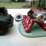
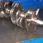
This is a rather simple trick and makes installing the 4.7L timing set a breeze! In short, all you need to do is lay out your sprockets and timing set out on a large clean sheet of cardboard and zip tie them in a way that will allow you to slide it all onto your engine as one piece.


The Crank sprocket is the only one that will not be able to zip tie into place. So pay extra attention to the timing marks as you install and after completion.


As you can see, the zip ties are arranged in a way that will allow the sprockets to be mounted on the cams and the crankshaft.

Do not undo the Zip Ties or pull the tensioner pins until everything is mounted and timing marks positively triple-checked.
** CAUTION ** – Be sure to check that your camshaft keys are lined up with the keyholes on the sprocket and where not “Compressed” into the cam. This is a common mistake that more than a few people have made… Make sure all key ways align and are positively engaged on both cams and the crankshaft.
Ensure proper torque on both Camshafts and Crankshafts! Failure to comply will result in loss of timing and possible damage to the engine.
Always start with the basics first. Your engine (no matter who built it) is an air pump (plain and simple). The more efficiently you get the air in and the more efficiently you get it out, the more power you’ll make. Simple Intake and Exhaust modifications are always the least expensive route and can even increase your fuel economy. Not to get into the technical details, here’s a simple list to follow:
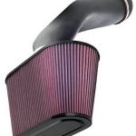
- Install a Cold-Air Kit (K&N, Intense Performance, PaceSetter, etc.)
- Install a Performance Muffler (Flowmaster, Dynomax, and Gibson are just three of many out there)
- Install a 180 Degree Thermostat (Keeping the engine slightly cooler makes more power. The factory 195+ T’Stats are mainly for emissions purposes)
- A good set of Spark Plug wires, Brass Contact Cap and Rotor, and a quality set of plugs will always help out your ignition system (DIS, or “Distributor-Less” ignition systems not included in this recommendation)
- Run a quality fuel. Chevron or Exxon are good choices…just stay away from the “Mom and Pop” stations. Putting old or dirty fuel in your tank won’t help your engine. Also, try to stay away from your favorite gas station when they’re filling up the tanks. Any sediment on the bottom of the tank will be mixed in with the new fuel and may get into your tank.
Those are just the basics. There are many options on ignition systems, throttle bodies, headers, etc., but it all comes down to “What goes in, must come out”. Take care of that department first and you’re on your way to making more power.
If you change your oil at the recommended intervals (normally 3500-5000 miles), a good Non-Synthetic oil won’t hurt your engine one bit (unless it’s low-grade “El-Cheapo” oil). If you want those last few HP out of your engine or race your vehicle every weekend, switch over to Synthetic Oil. It will last slightly longer in your engine but does cost more than regular oil. Which do we recommend? We’re not going to recommend any since it causes problems between vendors and personal preferences.
This is recommended at every Tune-Up to prevent excess carbon buildup on the IAC plunger. In some cases, you’ll notice a slightly erratic idle quality. This is the first step in taking care of that problem. IAC = Intake Air Control (Solenoid).
- Remove the Air Hat from the Throttle Body
- Disconnect the sensor harness from the IAC Solenoid (Rear of Throttle Body)
- Remove the two Torx-25 Screws
- Remove the IAC Solenoid (Be careful not to lose the rubber O-Ring)
- Spray some Carb/TB Cleaner in the IAC port on the Throttle Body and let it sit
- Spray some Carb/TB Cleaner on the tip of the IAC Solenoid and wipe clean (Do NOT forcefully twist or push the plunger – You will damage the Solenoid. Wipe very gently.)
- Spray a little bit more Carb/TB Cleaner in the IAC port on the Throttle Body and wipe clean with a thin/lint-free rag
- Reinstall the IAC Solenoid (Make sure you don’t lose the rubber gasket on the solenoid)
- Reinstall the sensor connector and air hat
- Start the engine and let it idle for about 1 minute.
If you change items such as the Throttle Body, Headers, Ignition System (or any internal parts with aftermarket, performance parts), then you should reset the PCM. Items such as Plug Wires, Cap, Rotor, Spark Plugs, Muffler, and Air Filter (not intake…filter) don’t require this at all. The PCM will gradually relearn as you drive anyway…that takes about 200 miles for a complete long-term learn.
Most people think that cleaning the throttle body requires a can of Carb/Throttle Body Cleaner and a quick “wash” of the bores. This may work but only washes the dirt and cleaner down into your intake manifold where it can puddle up and break down the belly-pan gasket. Then, it also is pulled into the combustion chamber where it can foul up the spark plugs.
The proper way to clean your throttle body is to remove it from the engine (you’ll need a small pan, some compressed air, and a new throttle body gasket for this procedure):
- Remove your air hat from the throttle body
- Disconnect the sensor connectors (TPS, MAP, and IAC)
- Remove the four throttle body bolts
- Lift the throttle body up and away from the intake manifold (place a rag over the manifold opening to prevent anything from falling inside)
- Remove the three sensors (Do not drop them)
- Remove the three screws for the throttle linkage (Not required…can be done with linkage attached)
- Place the throttle body in a small pan and spray Carb/Throttle Body Cleaner in the bores, underside passages, and ports. Let soak for about a minute.
- Clean the IAC Solenoid – Refer to “How to clean the IAC Solenoid”
- Spray some more Carb/Throttle Body Cleaner in the bores and ports of the throttle body
- Wipe clean with a lint-free rag (baby diaper works well) and blow out all the ports with some compressed air (a small can from an electronics store works just fine).
- Reinstall all sensors, then reinstall on your vehicle with a new Throttle Body gasket (don’t forget to remove the rag)
ENGINE OFF – When the throttle is 100 percent open the voltage at the TPS is usually less than 5v. Sometimes between 4v & 5v
ENGINE OFF – When the throttle is 100 percent closed the “ideal” TPS voltage is .76 with the key on the engine off.
ENGINE ON IDLE – When the throttle is at idle 100 percent closed the TPS voltage will normally read between .5v & .8v
FYI – MORE IS NOT BETTER! Please use the “SETTING TPS VOLTAGE – (Throttle Position Sensor)” In our TIPS section for reference.
REASON – The reason you would want to adjust your TPS sensor is to increase throttle response or to adjust a sensor that is not giving the correct voltage at WOT & Idle.
The object is to turn the sensor to alter the voltage up or down.
Some people have filed the threads down on the screws that secure the TPS sensor to the throttle body in order to gain more movement In some cases that’s all they needed to get the correct voltage reading.
The most popular way is to press out the brass inserts which create much more room for adjustment.
FYI after those inserts are removed your ability to set the sensor correctly has become CRITICAL. The inserts installed will get it close enough for factory specs… but removed you must set the TPS correctly or you will have all sorts of drivability issues.
The more you’re able to twist it counterclockwise, the higher the voltage will go. Remember to use the “SETTING TPS VOLTAGE – (Throttle Position Sensor)”
If your voltage is too low and you need more room to adjust you can remove the copper inserts to give it enough play to reach the right voltage.
Remember to check the voltage AFTER you have tightened the screws. If you tighten the screws too much you’ll even lose voltage because screws tighten clockwise. To verify your voltage after setting and completing the task.
There are 7 different modes (conditions) that are used (besides Key-ON and Key-Off mode). Here is a table of what sensors are monitored and what determines the mode. One thing to remember, under OPEN LOOP Operation, the O2 Sensor(s) are ignored by the PCM.
Engine Start-Up Mode (OPEN LOOP)
Battery Voltage
Coolant Temp
Crank Position
Intake Air Temp (IAT)
MAP
TPS
Starter Motor Relay
Cam Position Engine Warm-Up Mode (OPEN LOOP)
Battery Voltage
Coolant Temp
Crank Position
Intake Air Temp (IAT)
MAP
TPS
Cam Position
Park/Neutral Safety Switch (Automatics Only)
Idle mode (Once at Operating Temp: CLOSED LOOP)
A/C Select (if equipped)
A/C Request (if equipped)
Battery Voltage
Coolant Temp
Crank Position
Intake Air Temp (IAT)
MAP
TPS
Cam Position
O2 Sensors
Park/Neutral Safety Switch (Automatics Only) Cruise Mode (CLOSED LOOP)
A/C Select (if equipped)
A/C Request (if equipped)
Battery Voltage
Coolant Temp
Crank Position
Intake Air Temp (IAT)
MAP
TPS
Cam Position
O2 Sensors
Park/Neutral Safety Switch (Automatics Only) Acceleration Mode (OPEN LOOP)
A/C Select (if equipped)
A/C Request (if equipped)
Battery Voltage
Coolant Temp
Crank Position
Intake Air Temp (IAT)
MAP
TPS
Cam Position
Vehicle Speed Sensor
Park/Neutral Safety Switch (Automatics Only) Deceleration Mode (OPEN LOOP)
A/C Select (if equipped)
A/C Request (if equipped)
Battery Voltage
Coolant Temp
Crank Position
Intake Air Temp (IAT)
MAP
TPS
Cam Position
Park/Neutral Safety Switch (Automatics Only)
Vehicle Speed Sensor Wide Open Throttle – WOT (OPEN LOOP)
Battery Voltage
Coolant Temp
Crank Position
Intake Air Temp (IAT)
MAP
TPS
Cam Position
Diagram from AEM
RED (Power) – Connect to a switched 10-18 volt power source utilizing a 10A fuse.
BLACK (Ground) – Connect to clean power ground.
WHITE (Analog Output) – Connects to any Stand Alone ECU unit that accepts a 0-5 volt input.
BLUE (Serial Output)(optional hookup) – Connects to an RS-232 com port for hyper-terminal data logging.

Diagram from SCT
Black – General Ground
Orange – Analog Input #1
Blue – Analog Input Ground #1
Red – Analog Input #2
Green – Analog Input Ground #2

Connect AEM White to SCT Orange | Connect AEM Black to Vehicle Ground and SCT BLUE
AEM Wideband Formula in Air Fuel Ratio = (v*2)+10
AEM Wideband Formula in Lambda = (v*0.078557)+0.751
If you have any ground offsets, add or subtract them from the voltage (v). For example, for a .125 voltage offset, ((v-.125)*2)+10. Your gauge should match the reading on the tuner/livelink exactly.

